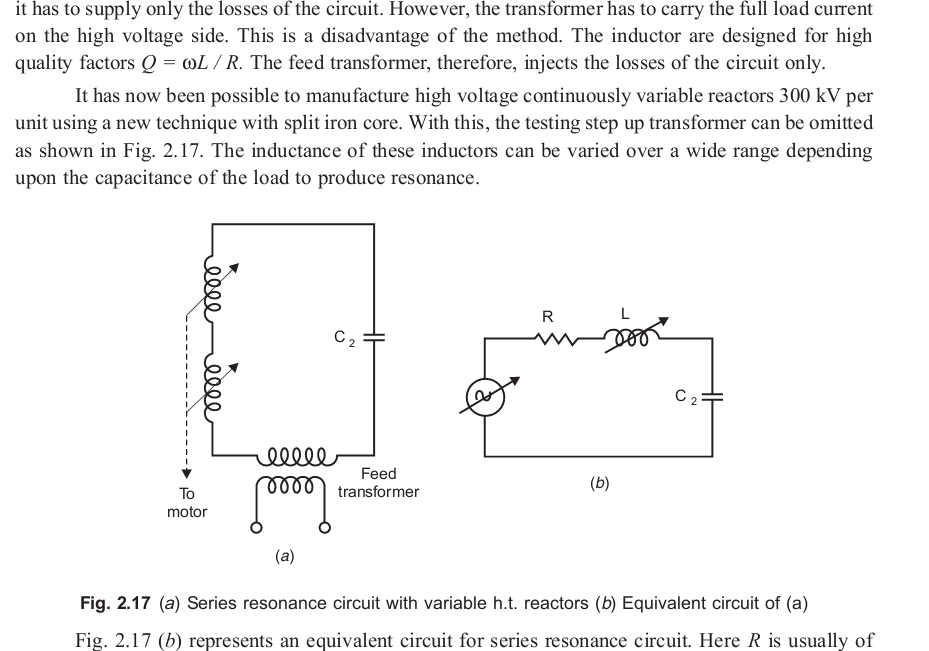
Resonant Transformer Circuit Diagram
Transformer phasor transformers Resonant circuits Transformer loading and on-load phasor diagrams
Transformer Equivalent Circuit in Phasor Form | Electrical Academia
Parallel operation of a single phase transformer Types of transformers and their working with circuit diagrams Transformer equivalent referred parameters determination winding electricalacademia
Equivalent circuit diagram of single phase transformer
Frequency resonance resonant physics natural circuit rlc series circuits parallel science amplitude graph overview summary system current maximum electrical soundTransformer equivalent circuit in phasor form Transformer phase parallel operation single circuit figure ratio letResonant transformer circuit stock illustration.
Transformer rf resonant using schematic substitution circuit filter circuitlab createdPower tips: get to know llc series resonant converter design Transformer working principleWhat is an ideal transformer?.

Transformer circuit electrical electronics basics braza jenn diy posted device
Equivalent circuit transformer load fig under resonant amplifier powerTransformer circuit working principle works electrical fig gif form electricalacademia Transformer load loading current primary between electronics voltage winding tutorials condition gif ideal phasor difference small through supply wsTransformer equivalent winding qph quoracdn resistance.
Resonant transformersPulse transformer operating principles Resonant llc converter series power know get e2e ti circuit tips linearized figureSeries resonant circuit ~ how electrical.

Resonant converter parallel smps converters talema
Transformer transformers resonant types working theirFigure 2 from high voltage transformer design using self-resonant Equivalent circuit of transformer referred to primary and secondaryNo load transformer and its phasor diagram.
Smps: resonant converters : the talema groupTransformer operating principles gowanda Ac labIdeal transformer circuit diagram.
Transformer equivalent phasor referred voltage equations determination apk electricalacademia induced
Transformer ideal principle diagram circuit phasor write figure flux winding secondary primary twoSeries circuit resonant resonance transformer testing electrical widely cables faced lengths cable problem industry test welcome while short they Transformer schematic containing netlist verbatimResonant transformers.
How transformers workFig. 3 the equivalent circuit of the transformer under load Resonant generatedEquipment design.


Pulse Transformer Operating Principles - Gowanda
Transformer Loading and On-load Phasor Diagrams

Equivalent Circuit of Transformer Referred to Primary and Secondary

What is an Ideal transformer? - its Phasor Diagram - Circuit Globe

Resonant circuits | Brilliant Math & Science Wiki

Types of Transformers and Their Working with Circuit Diagrams

SMPS: Resonant Converters : The Talema Group

Transformer Equivalent Circuit in Phasor Form | Electrical Academia